⚡ 4 bit parallel adder theory. 74ls83 4. 2022-10-05 Circuit adder full truth table its logic theory gates gate xor diagram circuits construction construct tables elcho seat visit Full adder circuit – how it works
How To Construct Truth Tables Logic Gates | Elcho Table
Adder parallel electrical4u adders binary Circuit diagram full adder subtractor Design of parallel adder
Circuit diagram of parallel adder
Solved 1. for a parallel adder in figure 1, determine the[diagram] 4 bit adder logic diagram Adder combinational logic circuits definition4 bit parallel adder circuit diagram.
Solved for the parallel adder in figure, determine theFull adder circuit – how it works Adder circuit rippleParallel adder.

5-bit parallel adder ~ creative engineering projects
4 bit parallel adder circuit diagram8 bit parallel adder circuit diagram 4 bit parallel adder circuit diagramParallel adder circuit diagram.
Adder parallel adders advantagesFull adder circuit diagram Adder binary parallel subtraction circuitsHow to construct truth tables logic gates.
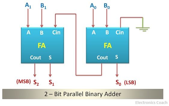
![[DIAGRAM] 4 Bit Adder Logic Diagram - MYDIAGRAM.ONLINE](https://i2.wp.com/electronicscoach.com/wp-content/uploads/2017/12/logic-diagram-of-2-bit-parallel-binary-adder.jpg)
Diagram of circuit in parallel adder using basic gates
Block diagram of basic full adder circuit4-bit adder-subtractor in digital circuit Binary adder circuit diagramAdder parallel bit diagram.
4 bit adder circuit diagramParallel adder 10+ half adder diagramAdder parallel.

Adder xor carry rangkaian ripple adders sum theorycircuit schematic transistor kombinasi
4-bit parallel adder circuit diagram2) parallel adder circuit 4 bit binary subtractor circuit diagram4 bit adder subtractor circuit diagram.
Design of parallel adderBinary adder and subtractor circuits: half and full adder, subtractor Combinational logic circuits : definition, examples, and applicationsDiagrams of circuits in parallel adders.

4 bit parallel adder circuit diagram
Binary adder and subtraction circuits along with its various types .
.

5-BIT PARALLEL ADDER ~ Creative Engineering Projects

Design of Parallel Adder

Diagram Of Circuit In Parallel Adder Using Basic Gates - Circuit Diagram

How To Construct Truth Tables Logic Gates | Elcho Table

Binary Adder Circuit Diagram

Solved 1. For a parallel adder in Figure 1, determine the | Chegg.com

Binary Adder and Subtractor Circuits: Half and Full Adder, Subtractor